Incontrovertible experimental proof is offered here that Faraday's Law of Induction is applicable to inductively suspended flywheels.
Thursday, January 28, 2010

Tuesday, January 19, 2010
Experiments 2.6
Shed dwellers and others,
You can see the results of the jan 14-19 experiments here.
The latest experiments and the experiments of jan 12, 2010 are conducted with the spin orientation of the wheels being (->, ->).
As the specific experiment of jan-7-2010 was conducted in the (->, <-) configuration, no lift was expected and none received. The net angular momentum of that system was zero (the opposite directions cancel out). Thats why it manifests strictly 'internal' events. For instance, the Kidd Effect, where the wheels move inwards with considerable speed and agility. The Kidd Effect is a powerful indicator that the system is producing a real force - one that can be harnessed. Its the sign of a jabberwock in the cage. In order to make this internal force exert itself on the outside, I reversed the direction of spin of one of the wheels. This meant the net angular momentum is adding up. Given my theory about inductively suspended flywheels being analogous to electrical inductors, the situation of expt 2.5 where the wheels are oriented (->, ->) is like having a live inductor with current flowing through it. Therefore whatever other people call the movement (deflection, precession etc), they are all taking about an inductively realized voltage, as far as the theory is concerned, since a voltage (in our case an angular velocity) is the result of a variable current (in out case a variable torque). This inductively realized voltage is obviously following the input pattern of sinusoidal amplitude. This is to be expected.
Further, using the frequency as a kind of controlling measure, I am able to reduce it to determine the characteristics of the upward movement.
For instance, it tells me that
a) Just like output voltage is tied to input rate of change of current in an inductor, the amplitude of the upwards lift momentum generated is determined by the rate of change of torque of the vertical motor. Notice that for the 9 second experiment, I only applied 4 A max torque. But for the 4 second experiment, I was at 8 A max torque. Thus, by reducing the rate of change of torque, I have reduced the output lift momentum. (thus reducing the amount of torquing going on).
b) However, my analogy with inductos also tells me that the output force is tied to the input momentum. Therefore, unless I can get the spinning flywheels -via their carriages to also build up a singnificant angular momentum, I will not be able to generate FORCE in the vertical direction. I can do this by playing with - the FREQUENCY of the oscillation and the max torque. You see how when we went from 4 seconds to 9 seconds, we went from making half circles to 2+ circles for certain torques. (Similar increases occured at all torques applied). So you see that I can build input momentum -within limits since I dont want to tip the machine over. So the idea is to keep amplifying the input momentum until we arrive at a suitable output that consists no just of momentum, but also force - since only force can cancel out gravity and impel the device truly upwards (and not around a center, as a torque would).
Cross-check: Our theory is confirmed by the behavior of a gyro on an Eiffel Tower. There, the precessing gyro has neither any oomph (force) in its precession, nor any momentum downwards (because of gravity). The idea is that the two quantities are related - i.e., In a precessing gyro only as much force is available to apply upon an obstacle encountered in the precession orbit as there is availability of rate of change of momentum about the input torque axis. Since the gyro on the Eiffel Tower has no momentum towards the earth (gravity is cancelled out leaving the tower without any movement downards), therefore it has no force with which to resist obstacles it encounters in its path.
We are going to give the gyro a backbone by working with the harmonics to give it angular momentum about the input axis. This will give the OUTPUT precession velocity of the gyro an additional characteristic - that of ACCELERATION. i.e., force. Theoretically, this can be mathematized by treating the acceleration as being due to the torque arm of the deflecting torque getting longer and longer so that the torque happens about a point further and further out towards the horizon, so that effectively, the torque becomes manifest as a straight force upwards. i.e. a rotation is acheived about distant points near the horizon of the inertial frames involved, converting a torque into a pure force.
You can see already, for example that in going from 4 seconds to 9 seconds alone, it seems as if the point about which the rel.machine is swinging when it tips over, has moved outward. Watch Expt 2.5 part 1 carefully and note what points on the ground the machine appears to try to tip over. Its the points that are almost directly under the wheels. In fact, at 8 seconds ( expt 2.6 part 1), at the higher torques, the entire rel.machine is swinging about points on a circle that coincides almost exactly with the aluminum ring I have installed on the bottom of the machine. Watch that video carefully. That ring is at a considerably larger distance from the central axis of the machine than the wheels are. This is proof that we are on the right track. More to come soon.
Wednesday, January 13, 2010
Thursday, January 7, 2010
Experiment of Jan 7, 2010
Please note that there is one small omission from the main text at the beginning of the video - there are a total of 11 oscillations in each of the two experiments shown in the video.
2 oscillations at 1 Amp
3 oscillations at 4 Amp
3 oscillations at 6 Amp
3 oscillations at 8 Amp
Also, the wheel spins are orientated in a non-lift configuration and therefore no lifting effects are seen in the video. This is a strictly test experiment before the main experiments next week.
2 oscillations at 1 Amp
3 oscillations at 4 Amp
3 oscillations at 6 Amp
3 oscillations at 8 Amp
Also, the wheel spins are orientated in a non-lift configuration and therefore no lifting effects are seen in the video. This is a strictly test experiment before the main experiments next week.
Saturday, December 5, 2009
Planning the Steps Involved in Machining A Job
A CNC program is a series of operations performed for specific selections of the tool, for a specific orientation/fixation of the job and at a selected combination of settings of the machine.


The series of operations is decided by the design of the job. So lets start with a simple part such as that shown in the picture below.

Here is a picture of the stock available to you.

Based on the stock and the final object desired, we determine that we need to machine both sides of the stock. We also determine the specific procedures and tools needed for each side and make a list pertinent to each side.
Based on the two lists, we can already know some of the tools we need to load into the machine. In addition, we also need to determine if some of the steps need to be repeated with a finer tool for better finish. This is usually determined by the machinist after test running a piece to see the quality of the output and checking that against the requirements of the customer.
For the first side, we need the following procedures performed. Let us assume that we do not need to machine the two off center holes on the job drawing:
a) The top of the cylinder has to be faced in order to me make sure that the the surface is truly perpendicular to the height of the cylinder and to give it a smooth finish.
b) The central hole has to be drilled.
c) The chamfer on the outside rim has to be machined
d) The champfer on the inside rim has to be machined
This is what the job looked like after the first side was done.

For the second side, we determine that the following procedures need to be done.
a) The bottom of the cylinder has to be faced in order to me make sure that the the surface is truly perpendicular to the height of the cylinder and to give it a smooth finish.
b) The outer rim of the cylinder has to be machined for a smooth finish.
c) A large partial hole concentric with the central hole has to be machined.
This is what the job looked like after the second side was done.

Bob and I ran (alright, I admit I didn't write the program or pick the tools) the test run and determined that for the first side, step (c) needed a finishing step after the main step and the same repetition for step (d) for the first side and step (c) for the second side. Thus all in all, we actually ended up with 5 steps on the first side and 4 steps for the second side.
I find that CNC machines are very fascinating! Here is a shot of the machine in action.

Some useful tips to remember:
1. When you start a CNC machine at the beginning of the day, for the first job, you need to back off about a thousandth on your cutting tool calculations because everything is cold. This manifests as the cutting tool cutting a little less.
2. Conversely, I also observed the opposite - after several runs (this was a 200 piece order), the tool bits do expand from heating and you might have to move in another half-a-thou. Otherwise the holes you drill may be the slightest bit loose.
3. Unloading and Loading tools into a CNC: In order to change tools on a CNC, you can generally (although this is specific for Mazak) find a TOOL menu item which can be expanded to show several options. Choose the MDI (Manual Data Input) option. Then you will be prompted to enter the tool number you want to change (typically up to 10 tools) and hit INPUT. The machine will then move the tool block so as to present the request tool head to the user. Twist and pull out the tool.
Putting in the tool must always be done in the same way, with a large dot on the tool always positioned either to the front or the back (depending on the machine involved), so be aware that there is danger for misalignment if this is not observed.

Above you can see some of the finished pieces stacked together.
Tuesday, December 1, 2009
The Kidd Effect and Faraday's Law of Induction
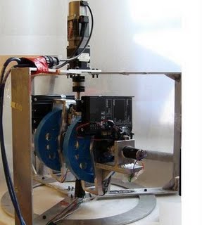

Consider the flywheels of the RelMachine. They are mounted in frames, on ball bearings to facilitate their smooth rotation. The frames themselves are affixed to the (rotatable) central machine axis. When we rotate the flywheel assembly about the central axis of the machine, what are the conditions that obtain? The flywheels have mass. They are being spun about the central machine axis. Under such conditions, the flywheels are being acted upon by the machine axis - the machine axis is exerting a centripetal force.
Wikipedia
http://en.wikipedia.org/wiki/Centrifugal_force
A mass undergoing curved motion, such as circular motion, constantly accelerates toward the axis of rotation. This centripetal acceleration is provided by a centripetal force, which is exerted on the mass by some other object. In accordance with Newton's Third Law of Motion, the mass exerts an equal and opposite force on the object. This is the "real" or "reactive" centrifugal force: it is directed away from the center of rotation, and is exerted by the rotating mass on the object that originates the centripetal acceleration.[5][6][7]
The concept of the reactive centrifugal force is used often in mechanical engineering sources that deal with internal stresses in rotating solid bodies.[8] Newton's reactive centrifugal force still appears in some sources, and often is referred to as the centrifugal force rather than as the reactive centrifugal force.
Now, so far the flywheels haven't themselves been spun up. Therefore, in accordance with Newton's laws, the flywheel then exerts an equal and opposite centrifugal force upon the central machine axis.
What happens if we first set the flywheels spinning to a large, fixed rotational speed ω z rpm and only then started spinning the entire flywheel assembly about the central machine axis? The answer to that question depends on whether or not there is a significant rate of change of angular acceleration in the motion of the flywheel assembly about the main machine axis.
CASE A
If there IS a significant rate of change of angular acceleration, the answer proceeds as follows:
In order to extrapolate the expected behavior of the flywheel in this case, we reason that since the flywheel is inductively suspended, we must look to the behavior of an inductor. An inductor RESISTS a rate of change of current through it.
Thus when an inductor begins to feel the surge of rate of change of current, it will correspondingly generate enough potential difference to overcome and cancel that current so as to maintain its previous state. However, if there is even so much as a tiny bit of capacitance coupled to the inductor, them the together form an LC circuit and will therefore have a unique threshold frequency peculiar to them. - This is an element of a low pass circuit, which means that any and all frequencies below the threshold frequency will receive a 'pass' from this circuit.
The exerted surge can have a periodic character or can be more of a simple speeding up character. Lets analyze the two.
If the surge is cyclical for example like this, the analysis is perfectly analogous to the LC low pass filter circuit. Thus all such inputs will meet the 'pass' condition of the low pass filter circuit.

Under such conditions, the circuit will resonate with the energy and some of it will leak into the ambient surroundings. The equivalent of this in the mechanical case would be the SHEDDING OF CENTRIFUGAL FORCE.
If the surge is more just a transient thing on the way to acheiving a steady torque used to accelerate the assembly to a large angular velocity about the central axis, this is what the time vs angular velocity, acceleration and rate of change of acceleration will look like.

We can see that the inductive phenomenon will only be effective for the following time periods: the beginning when the wheels starts speeding up about the central machine axis, and at the end, when the flywheels were brought to a stop. Thus the effect would be transient and barely noticed excepted at the beginning and the end of the operation.
CASE B
If there isn't a significant rate of change of angular acceleration: This is similar to situations where the flywheel is spinning and the assembly itself is
i) being moved in approximately straight lines,
ii) or being moved at constant accelerations
iii) or being moved at constant velocities.
Under such circumstances, relativistic effects are hidden from our view. The phenomenon proceeds as a Newtonian interaction.
ANALYZING THE KIDD EFFECT VIDEO
We can see from the graph at the very beginning of the Kidd Effect video, that there is large rate of change of acceleration being deliberately induced by vertical motor at the top of the Relmachine, in a cyclical fashion. Thus the flywheels respond as in CASE A.
Now, some energy from this capacitance-inductance circuit will 'leak' into the surroundings i.e. the flywheels will shed centrifugal force. It means the flywheels will lose part or all of their ability to produce a centrifugal force in response to the exerted centripetal force. This shedding of centrifugal force has consequences. The most direct consequence is that if there is a way the flywheels can move, either inwards or upwards they will move. The conditions governing the movement are as follows:
1. The flywheels are spinning fast enough (condition 1) and the applied rate of change of torque is large enough (condition 2) to over the gravitational force acting downwards, and the force rquired to forcibly move the flwheel vertically is less than the force required to move the flywheel horizontally (condition 3): Flight will result.
2. If condition 3 is not met, then if the conditions 1 and 2 are met, then we see what happens in the end of the video, when the flywheels forced themselves inwards.
3. If condition 3 is met but 1 or 2 are not met, then the RelMachine will show no net movement, but will show a net leakage of energy because the energy channel is open. Just not full. As conditions 1 and 2 are fulflled, the channel will fill up and the relMachine will fly. Until then, the leakage of energy to the gravitational field will steadily increase as we increase our ability to meet conditions 1 and 2 (ie we increase the flywheel speed or the rate of change of acceleration).
ANALYZING SANDY'S FIRST MACHINE
In Sandy's patent, he exerted forces on the flywheels in a slightly different, but nonetheless very creative manner.
"means for periodically forcing said masses towards one another from a predetermined position and allowing said masses to return to said predetermined position so as to generate a pulsatile force in said mounting means."
US Patent # 5,024,112
Thus the wheels were physically pushed towards the central machine axis. This is equivalent to the RelMachine's operation. In the RelMachine, that 'pushing' force is being exerted by the centripetal force, which in Sandy's machine, it was being done by a cam, in a very physical way.
Thus, in the case of his machine too, a cyclical consistent amount of lift will be delivered. Depending on the match between the resonance frequency of his machine and the applied cyclical torque, the output could have been suboptimal.
NEXT STEPS
I have determined that at this point, I must amplify the output. I will endeavor to do so in the coming weeks. I expect to run new, amplified experiments within the next 3 weeks.
Saturday, November 28, 2009
Working On A 3-Axis CNC Turning Center
Operating lathes requires exceptional skills. Years of hands-on work hones the superior machinist. I am myself a neophyte - although I admit I did use sturdy old hand-operated lathes in Mechanical Engineering lab back in my University days to cut, trim, polish, drill and tap various prepared pieces of metal. So I'm not trying to give advice on CNC Machining here. I'm posting this so as to document what I'm picking up before I forget it all.
A 3-Axis CNC turning center is a combination lathe and computer that gives the user freedom of working in 3-Dimensions, X, Y and Z. The diagram below illustrates the coordinates system as related to the bed of the lathe. Being a lathe, it has a headstock with a spindle and a tailstock so that the job can be clamped securely and held that way and then spun at selected speeds to enable cutting operations. For small jobs, you can simply clamp the job to the headstock spindle. You can see a small AL 6061 job clamped to the headstock spindle below. You can also see the toolhead with multiple tools that the machine can switch on the fly for continuous operation.

CNC (Numerical Control) allows us to control the lathe using programming statements and commands. Take a look at the picture below to see the typical interface of one such 3-Axis Turning Center. The machine is operated by a combination of entering commands into the screen and by operating the knobs and levers.

Don't let the formidable looking interface fool you. Learning it is the easy part. By far, the harder part of machining is the set up. With the aim of minimizing the number of cuts you have to make, you have to figure out the exact series of operations you need to make. Simultaneously you have figure out the set up involved in each of those operations. If you want to minimize the time you spend on it (and trust me, it always takes longer that it should, its in the nature of the beast), then you getting the set ups figured out is the most important factor that counts. A major mistake such as overestimating the clearances of the job and the reach of the tool bit can cause a huge headache. You might have to drill with a drill bit thats too long and that will cause vibration issues. Planning the order of the operations is also fairly important, especially if they build on each other and remove material that is critical for certain other operations.
Many thanks to Bob, the Master Machinist!
Subscribe to:
Posts
(
Atom
)